This guide will help you install the Dreamcast controller board and clock battery repair kit. This will fix dead controller board and a dead Dreamcast clock battery. The kit has everything you need for this guide except the tools. The most common problems are a dead clock battery, which causes you to reset the clock when you boot the console, and a blown fuse, which kills all the controller ports. The other parts in the kit should fix the controller board if your dead port is caused by some other problem.
Be careful in this process not to damage your board. There are 2 main kinds of V1 or V2 controller port boards. There is a green style board (which is depicted in this guide) and a yellowish style board. Both boards are exactly the same but the manufacturing is different. The green board much more difficult to work with, since the parts don’t come out as easily, but it is much harder to damage. If you have a yellow board, the parts tend to easily fall out when you heat them but the board is easier to damage, be extra careful and don’t apply any more force than necessary getting these parts off. That being said it is still a very safe procedure if you are careful so don’t let this scare you away from doing it.
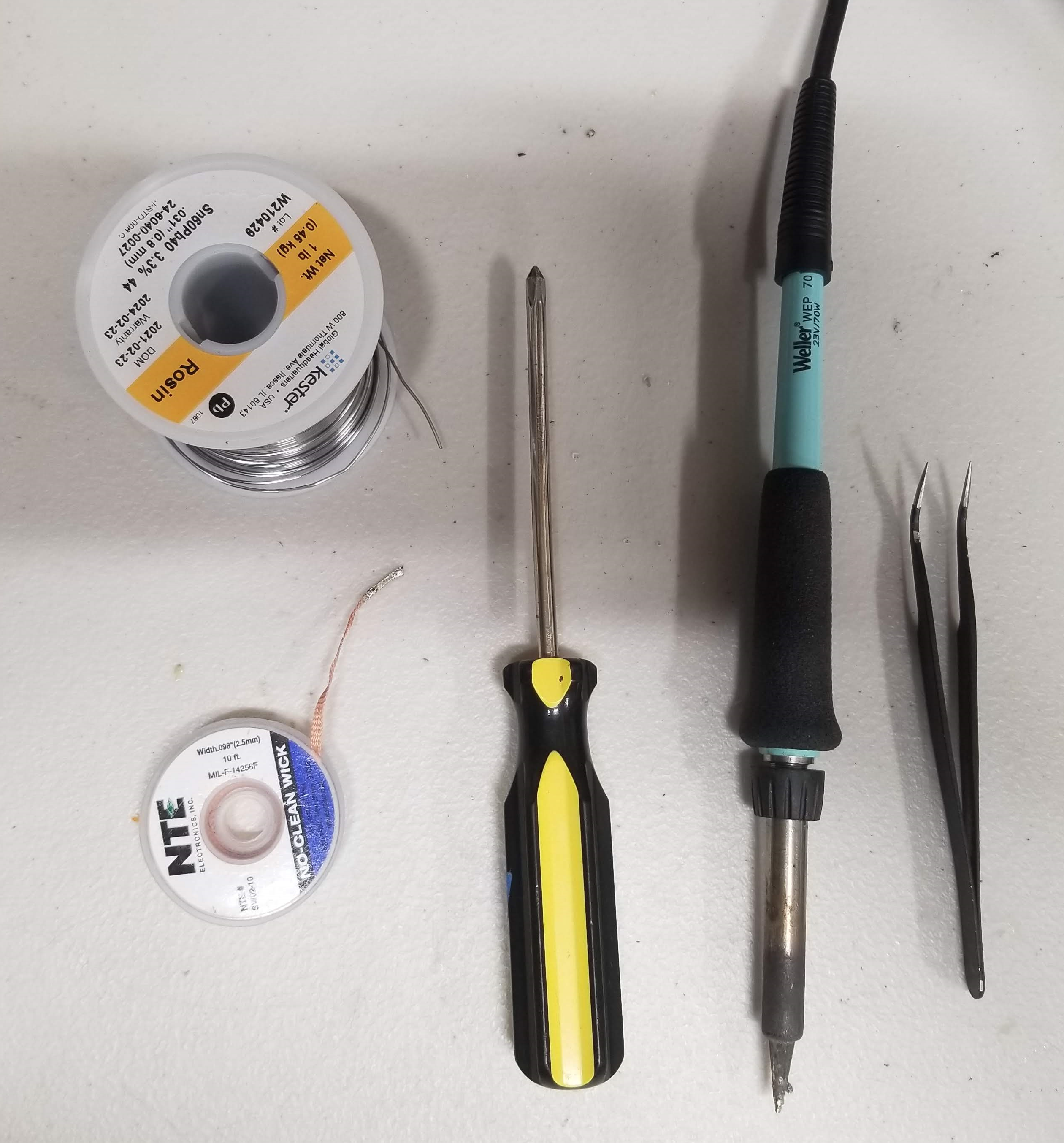
Tools Required For the mod
New Controller Board Parts (battery post, fuse, resistor, capacitor, battery)
Screwdriver
Soldering Iron
Solder
Tweezers (optional)
Copper Braid (optional)
Now lets Get To It
Pro Tip: An easy way to follow this guide is just to click the first image and use the arrows to go through each step.
This may be easier if you use a helping hand or vice grip or something to hold the board but this guide is meant to explain how to easily do it with as few tools as possible.
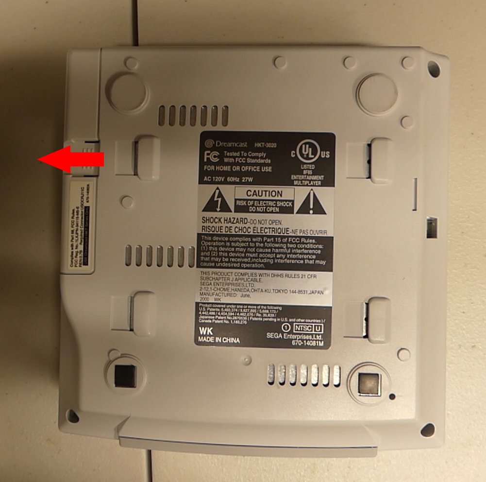
First you are going to want to remove the modem by pushing the bottom part and sliding it out
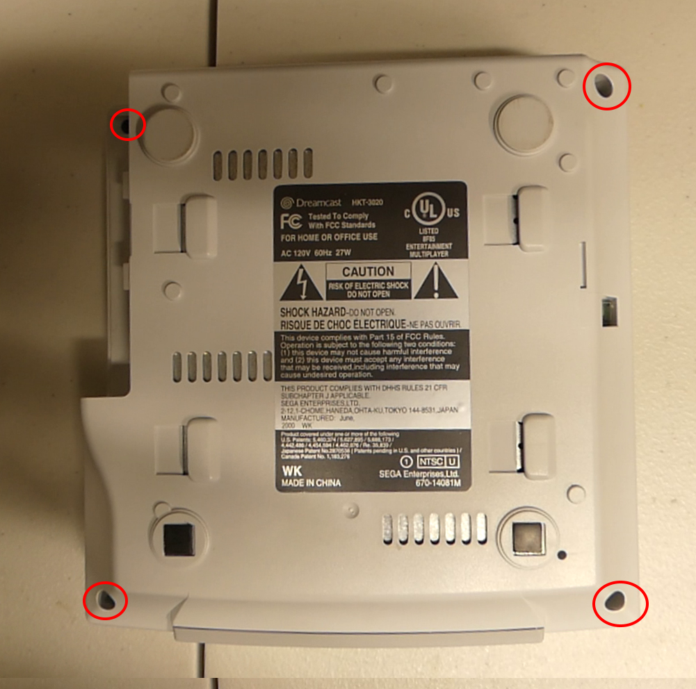
Then you can remove all four screws holding the top shell on. Turn the Dreamcast back over and lift off the top shell.
There are four screws you will need to remove outlined here to remove the controller board. You can carefully pull up the ribbon cable and remove the board.
1. The Battery Replacement
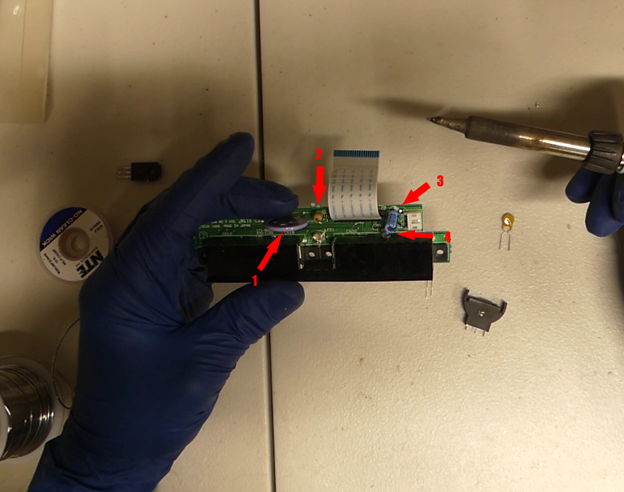
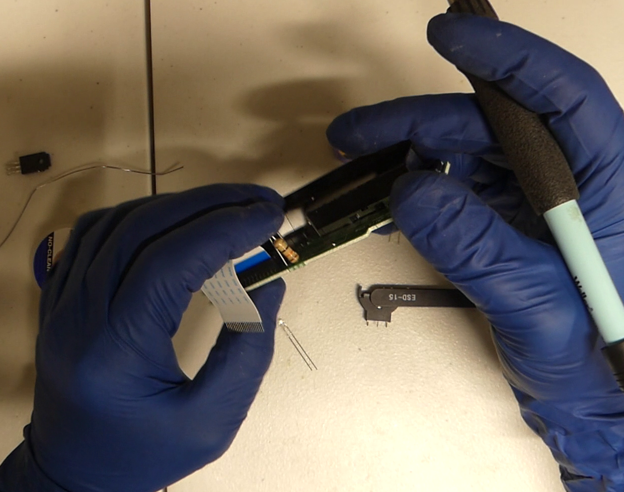
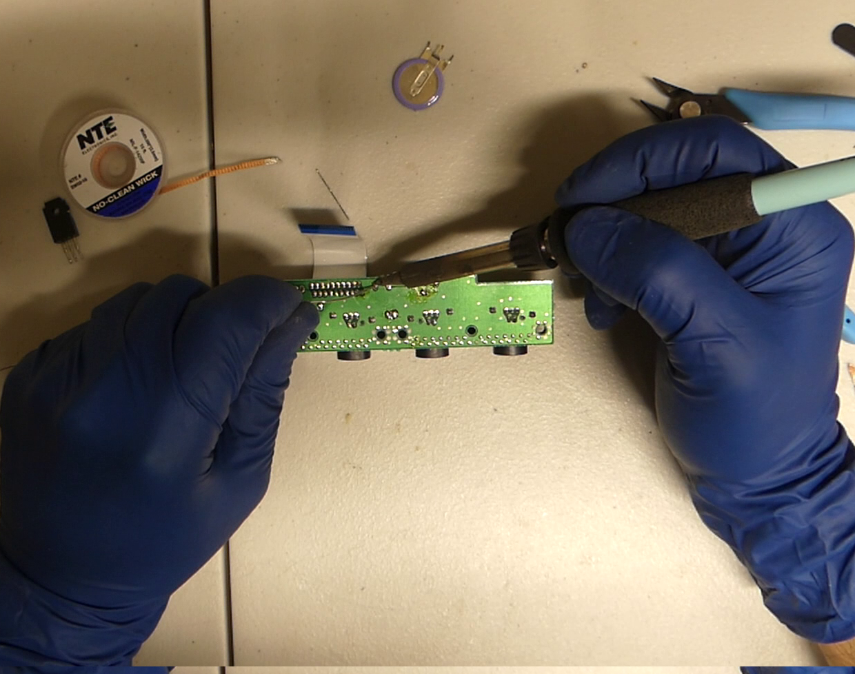
Now I have pointed out all the parts we will be replacing in the photo. Going sequentially they are the battery, resistor, capacitor, and fuse. If you have V0 console these will be in a different place.
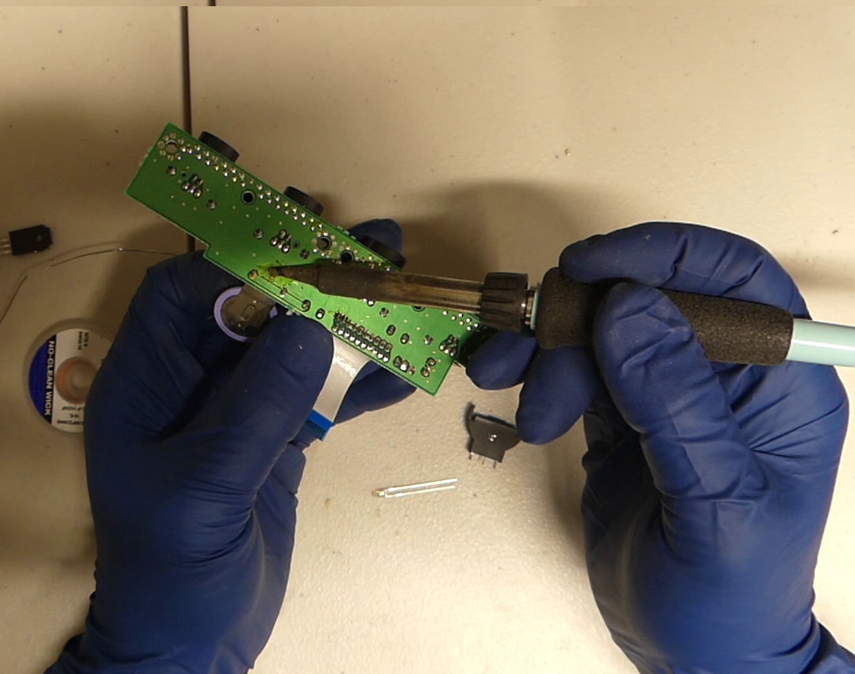
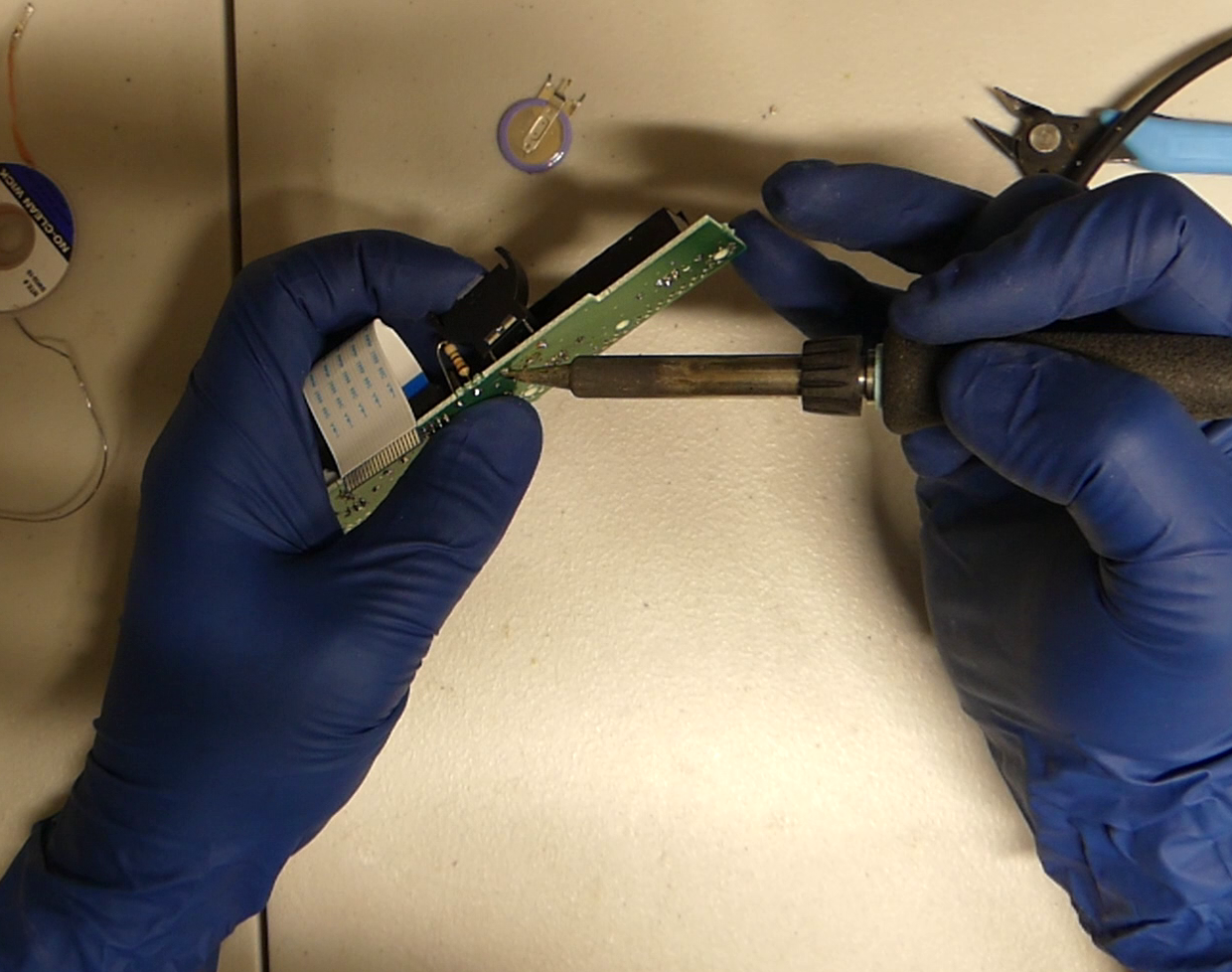
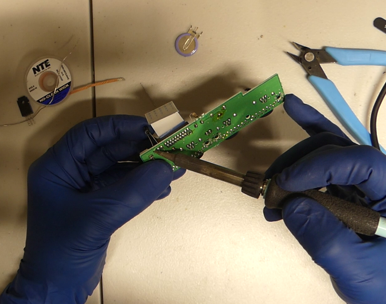
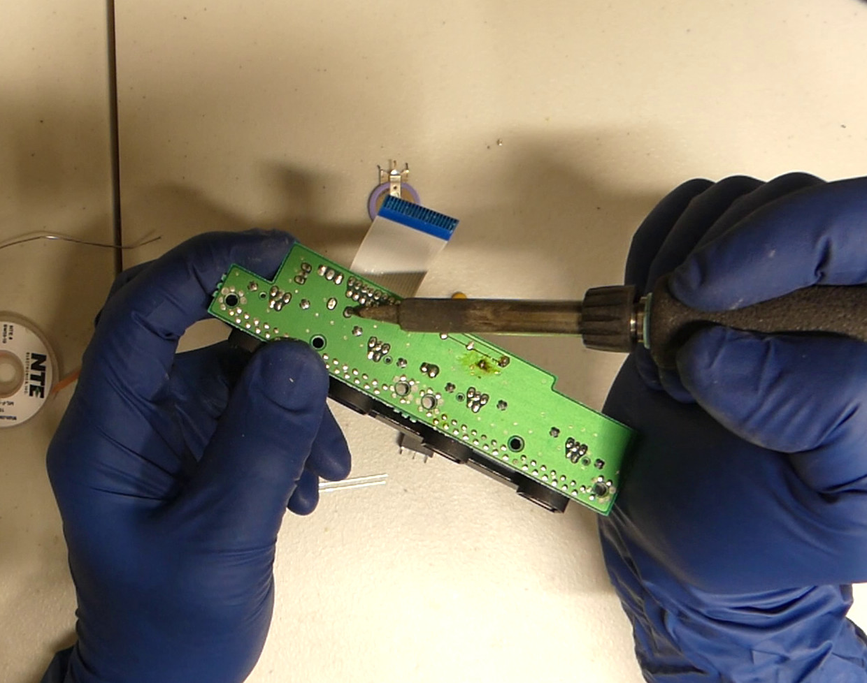
Lets start by removing the battery. Hold the board as I show with your index finger on the battery and give a small amount of pressure toward the palm of your hand.
Heat the point in the photo and the battery will slowly bend toward the palm of your hand as the pin comes out.
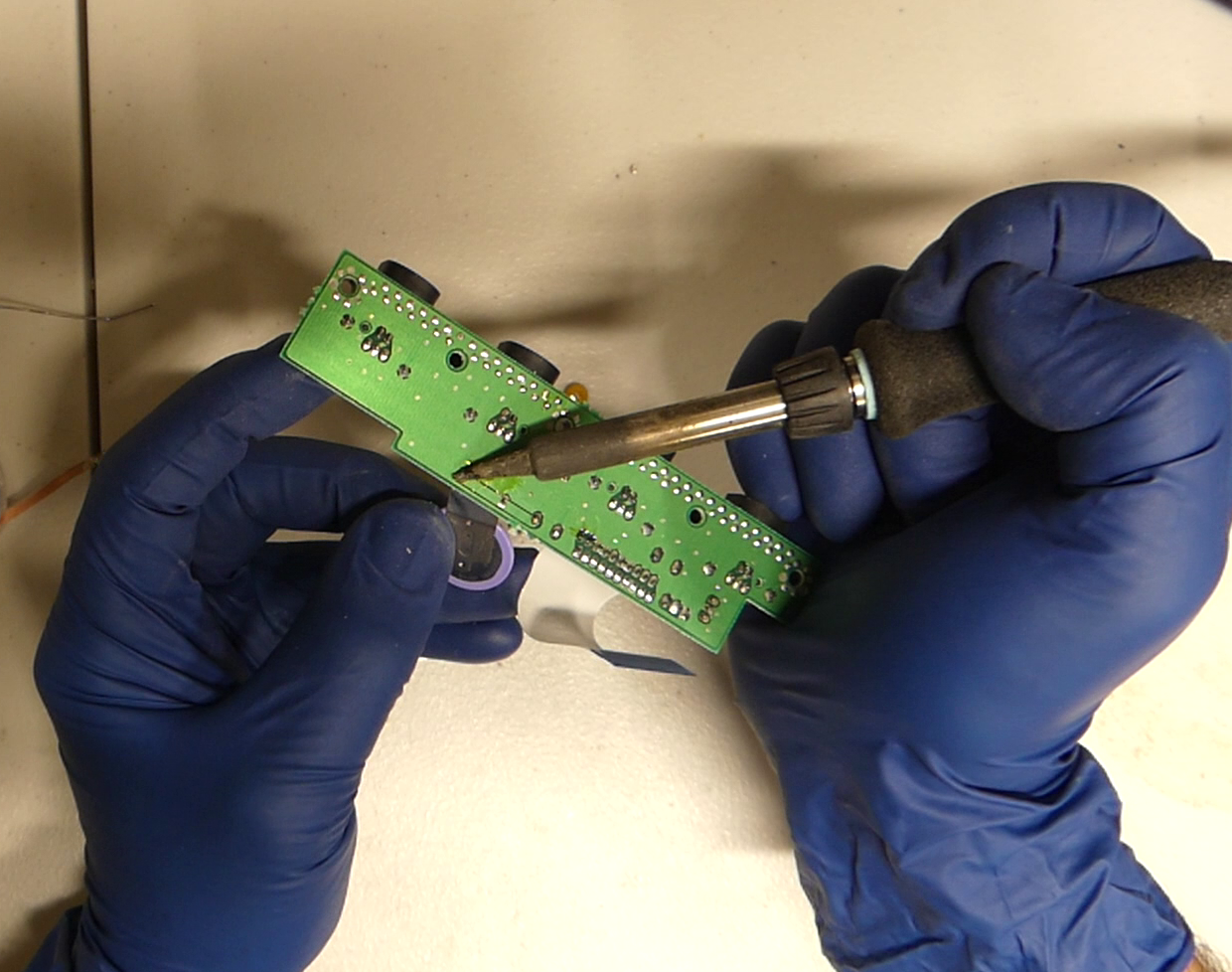
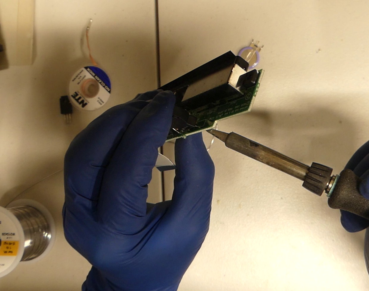
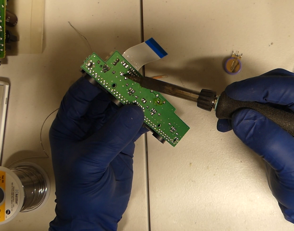
Move on to the next pin and you can pull lightly away from the board as you heat the pin.
For the last pin just apply a bit of heat and let the heat and gravity do the trick. It should fall out of place on its own.
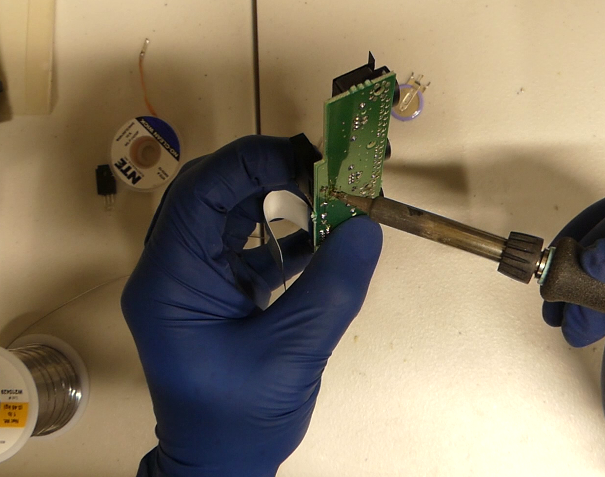
Now on some boards you will want to clean up some excess solder on the top so the battery pins can easily seat. If you have a blob of solder above the battery hole cleaning it up will make the rest of the job easier. Just apply the copper over it and heat to wick away the solder.
We will install the battery post in reverse order of removal. Sometimes the pins line up perfectly, if they do you can easily hold the battery with one finger as you solder each.
Otherwise you will want to line up the pin closest to the flex cable and hold it with your finger as you apply heat. Make sure there is enough solder on your tip here. When you feel the pin start to sink in remove the iron. Don’t push it all the way in or you will have trouble with the other pins
Next line up the pin farthest from the flex cable, it’s ok to bend the pin slightly to get it to line up. Applying pressure with your finger apply heat to the bottom of the board until it goes in just a little bit.
Do the same for the last pin. At this point when all 3 pins are in you can apply pressure to the top of the battery post and go around touching each pin with your soldering iron while applying pressure. It should sink a tiny bit further in each time you touch it until it is fully seated. Be sure to reflow the bottom of the board with a bit more solder when you are done.
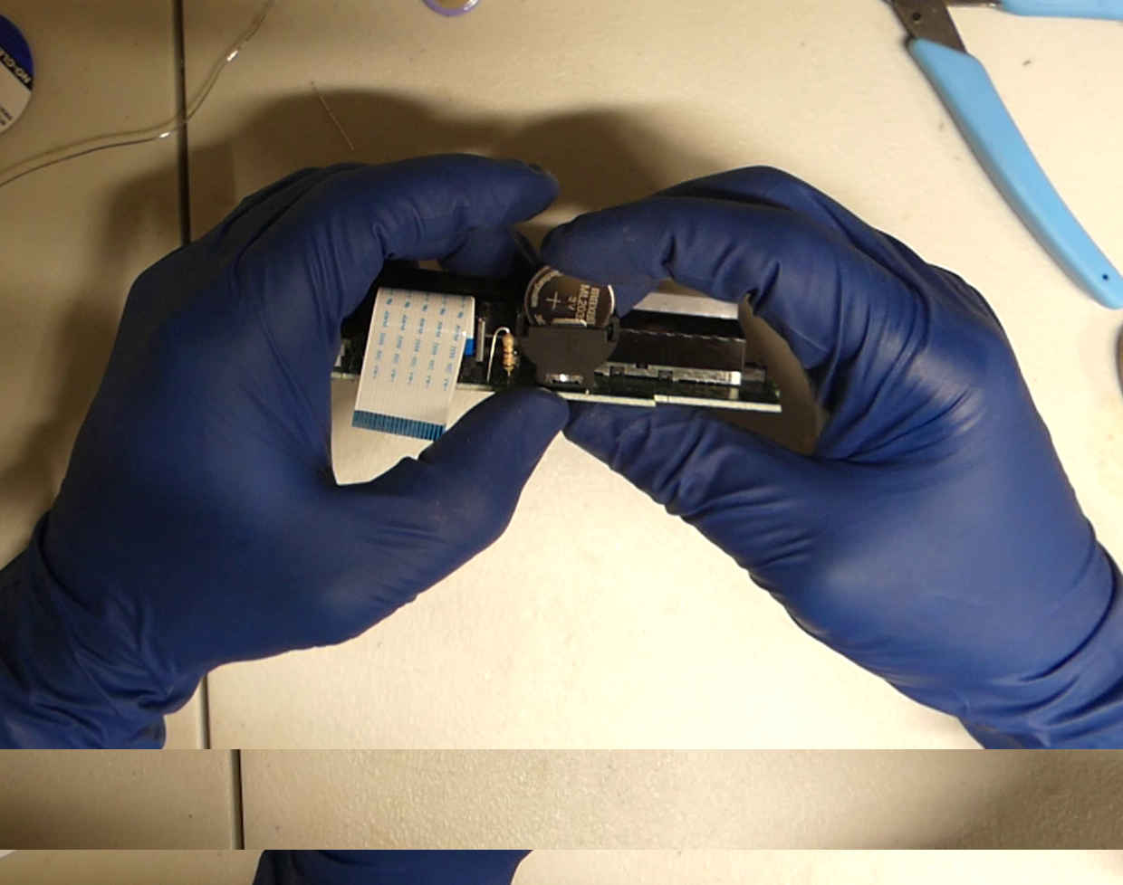
Slot the battery as shown with the positive terminal facing away from the controller ports.
2. Replacing the Resistor
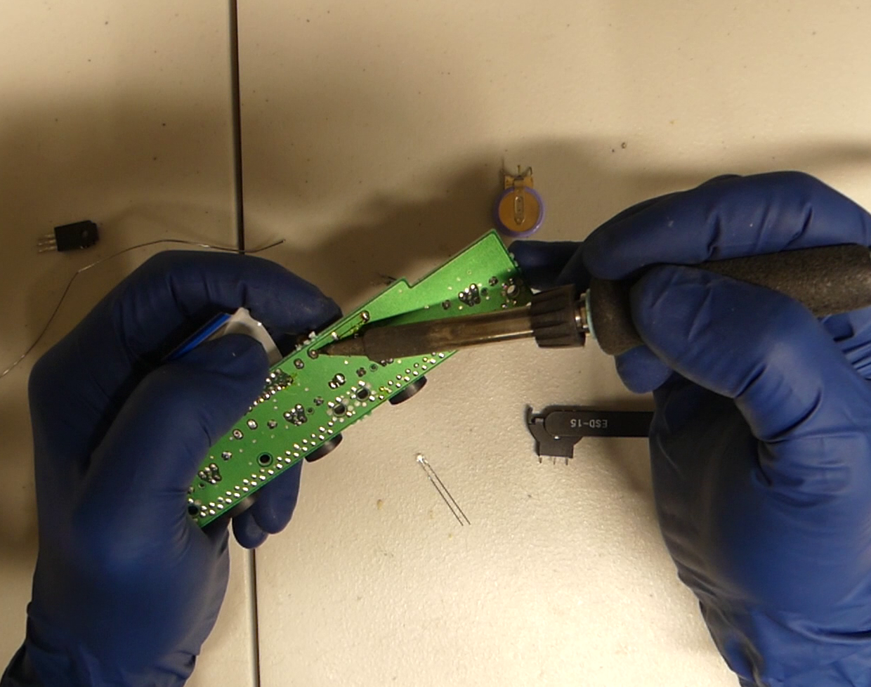
Put one finger on the resistor as shown and turn the board over. You will use your finger to apply pressure as you heat the bottom.
While heating the bottom of the board apply pressure with your finger away from the pin you are heating. When that pin comes out you can apply heat to the other pin and it should drop out.
Bend the resistor as shown. One leg will be longer. Align the long leg with one of the the resistor peg holes and use your finger to hold it into place. Don’t worry about which peg or hole you use, they aren’t directional.
While applying a bit of pressure to the resistor into the hole heat the bottom of the hole. It should slide right in until the short peg stops it. Then line up the short peg and do the same. At this point you should have both ends of the resistor in but not all the way. Now you will want to apply a small amount of pressure to the top of the resistor and go back and forth between each point with your soldering iron until it sits down far enough.
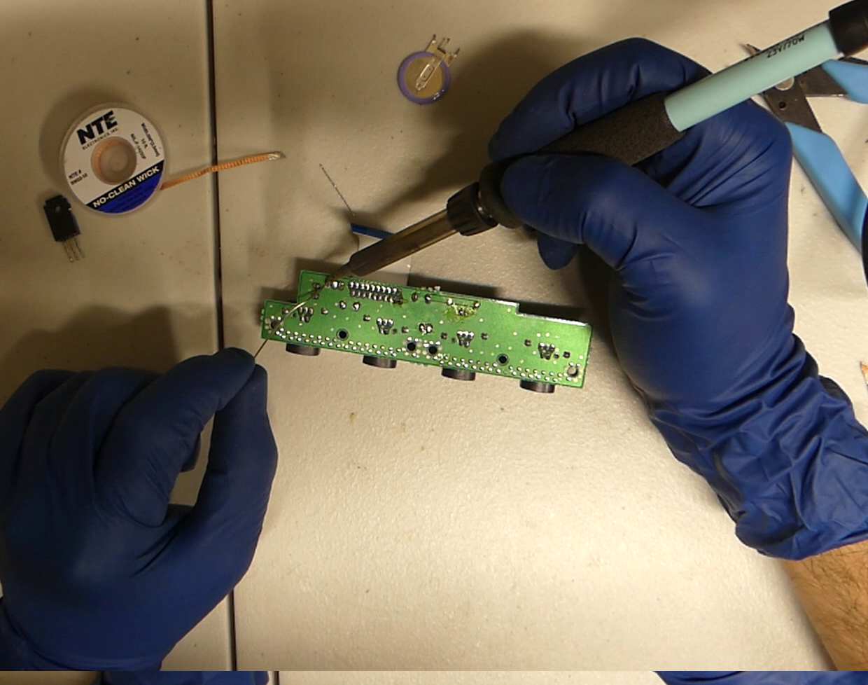
Be sure to clip the extra metal coming from the bottom of the resistor. Cut them as short as you can here.
Touch up the solder on the bottom by adding a little bit of fresh solder. If one of the holes is empty do that one first otherwise the resistor may drop back out of the board.
3. Replacing The Capacitor
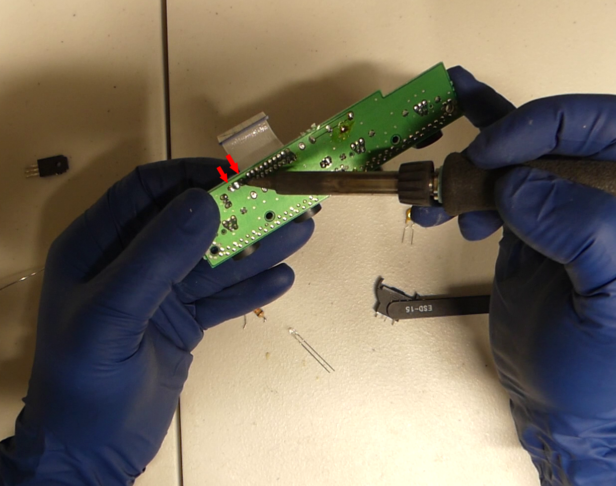
The removal is just like the resistor. Just put one finger on the capacitor and apply heat while applying pressure away from the pin you are heating. When you get the one pin out the second will drop out just by heating. There are three pads under the cap but only the two I have put arrows on are used.
Examine the capacitor, notice that on one side there is a “-” sign. That is the negative side. On the ones in the kit it is also the shorter peg. It is important to align the capacitor with the negative side toward the fan plug. Otherwise if you put this in backwards the cap will explode.
Now that we have the orientation down you can line up the longer peg (or in my case the positive peg) with its proper hole. In this case it is the farthest hole from the fan plug. Hold the capacitor in place with your index finger and apply heat to the bottom of the hole. It should slide right in until the short side hits.
Now line up the short peg to its hole and apply pressure with your finger as you heat the bottom of the board, remember that the center hole was not used. Walk the cap in by going back and forth between each pin while applying pressure until it is down low enough.
Trim the bottom pegs of the capacitor as short as you can.
Touch up the solder on the bottom of the capacitor and like before, if one of the holes is empty do that one first otherwise the capacitor may drop back out of the board.
4. The Fuse
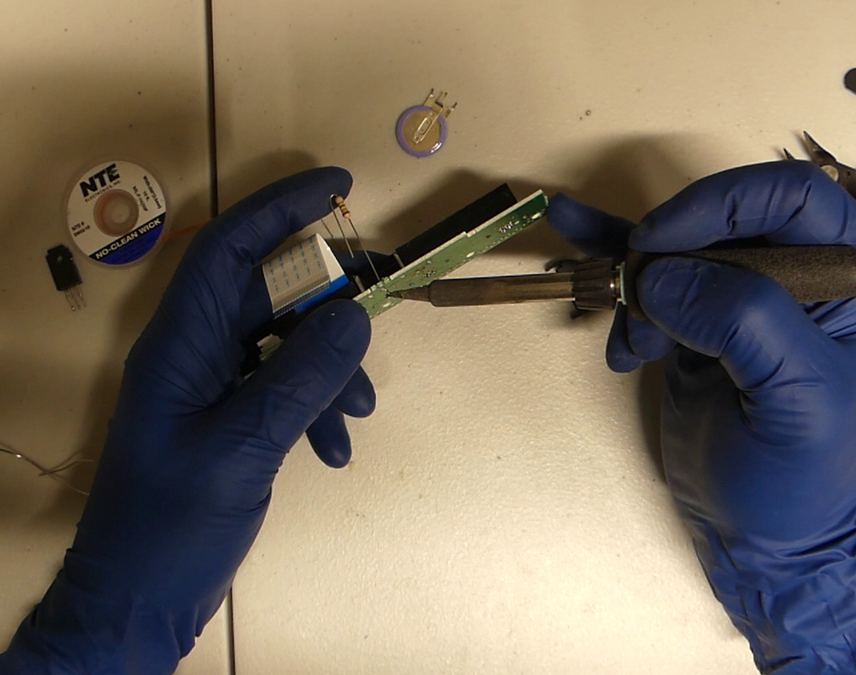
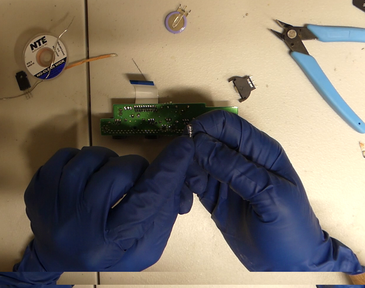
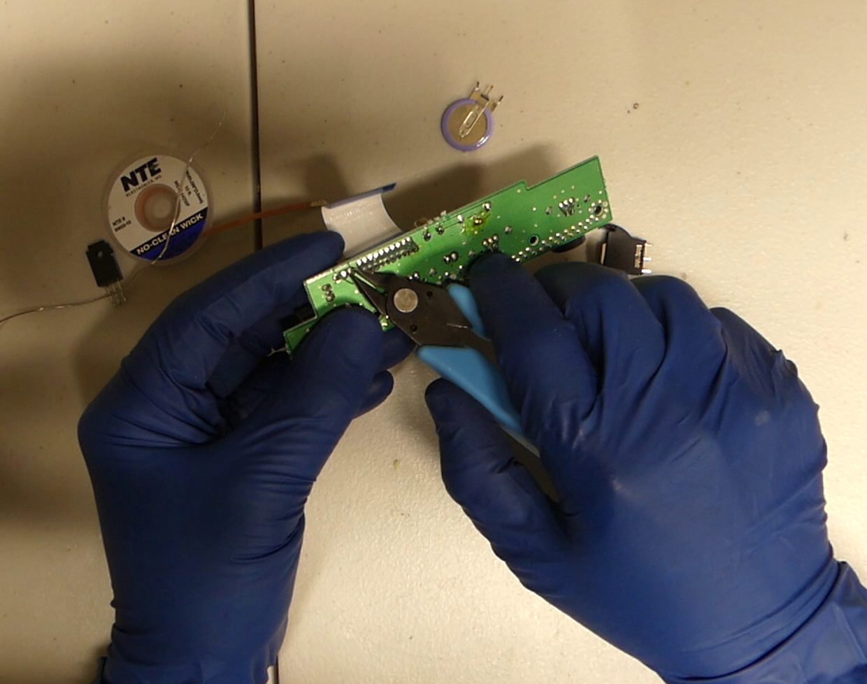
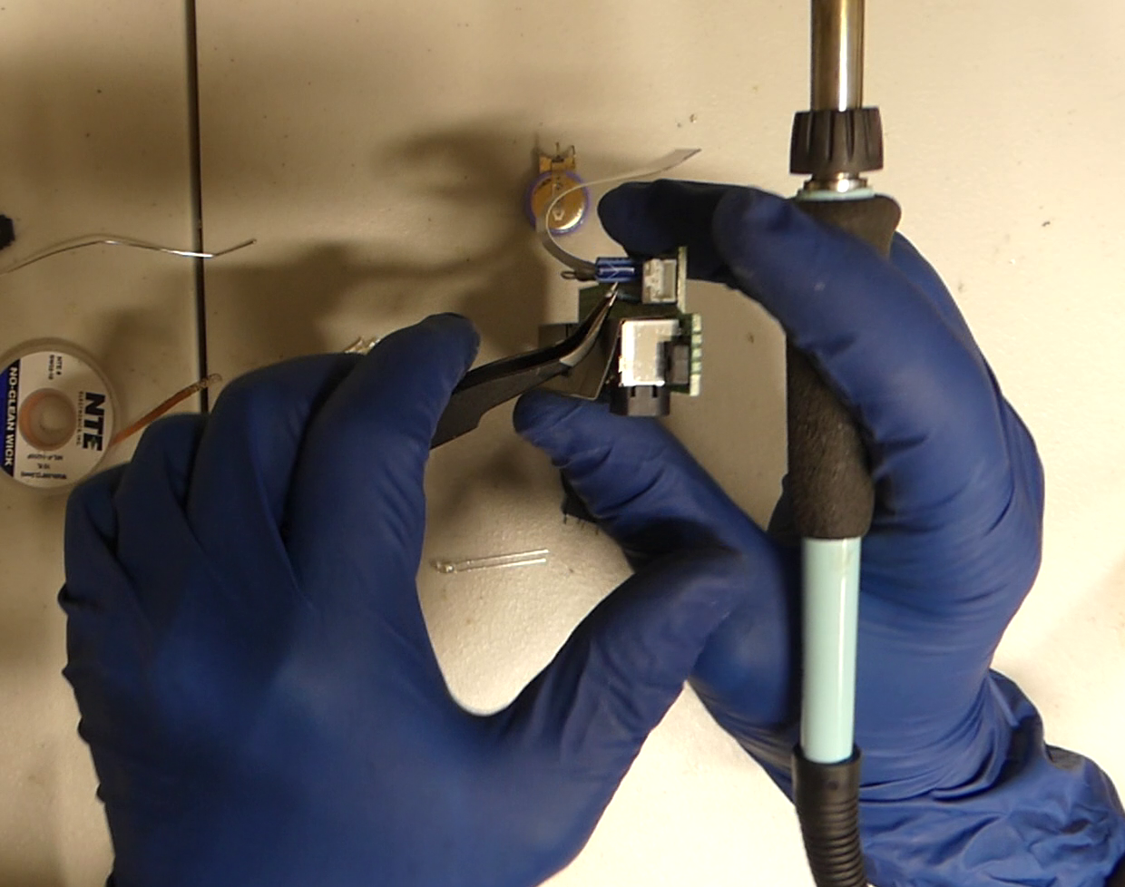
The easiest way to remove the fuse on one of the more difficult boards like this one is to hook it with a pair of tweezers as shown. You can hold the tweezers with your middle and ring fingers and hold the board with your index and thumb.
Apply a small amount of pressure to the tweezers to pull the fuse against the board using the controller port as a leverage point. While doing this just go back and forth melting each of the two solder points on the bottom of the board. You will feel it slowly drop out a little more each time until one side is out completely. Just heat and let gravity do the second side.
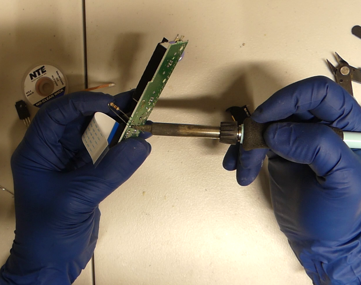
To put the new fuse in you can just line up both holes with the pegs and hold the fuse against the holes with one hand. You should be able to get both holes to line up. You may need to clean up the top of the board with copper braid as we did in the battery install if it will not sit in the center of the hole.
Apply heat to each hole back and forth. You should feel the fuse slowly walk in as you go back and forth. When you are done trim the pegs and reflow the solder. As before if one of the holes is empty do that one first otherwise the capacitor may drop back out of the board.
Finishing Up
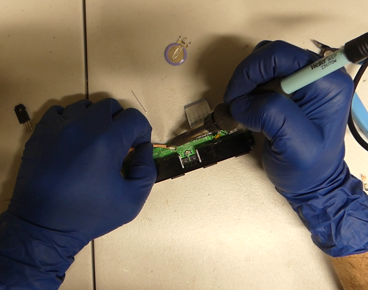
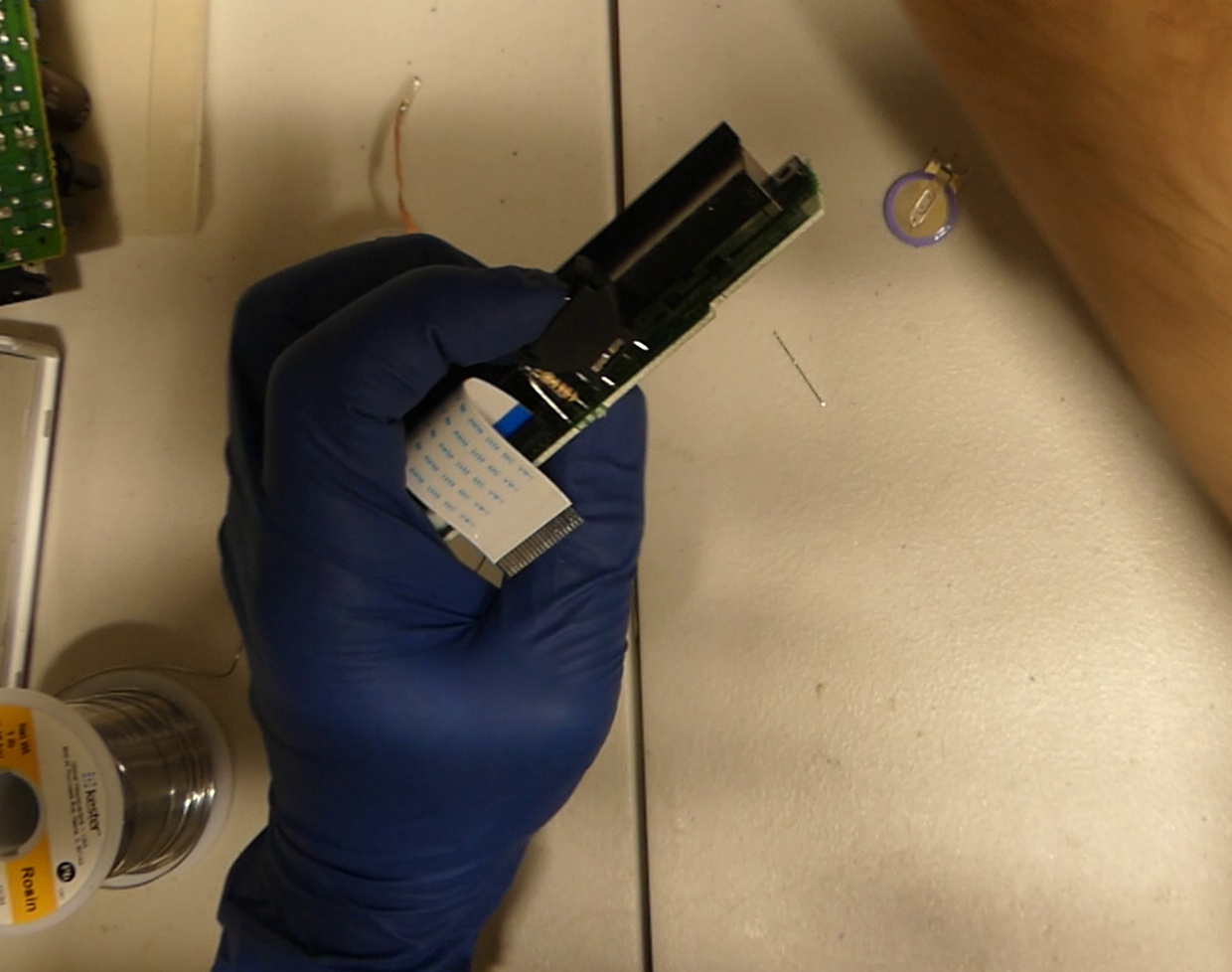
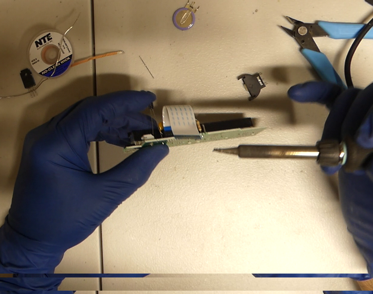
Put the board back inside, replace the ribbon cable and fan cables and reassemble everything. Pardon the missing pieces in the picture I was doing other mods in the video I snapped this from 🙂
Congrats your controller ports should be good to go and be sure to set the clock. One last note the battery may need some charging so the system will need to be on for that. Maybe it is time to spend an hour or so playing one of your favorite games.
The Video
If you would rather watch this as a video it is coming soon.